Device Overview
The USBug is a complete USB-based microcontroller development system in a very small footprint.
Programming is done via the USB port. No special programmer device is needed, only a standard “Mini-B” USB cable and a Windows/Linux PC or a Macintosh host computer with a USB port are required.
Key Features:
- Fully Open-Source Hardware & Software (CC-BY-SA, GPL)
- Drag & Drop firmware: just use it as an USB Memory Stick!
- No Loader application, the bootloader resides in ROM (unereasable and does not require precious Flash space)
- Works with Mac OS X, Linux & Windows
- SWD/JTAG connector (0.5 mil/1.27 mm pitch, standard SWD/JTAG connector)
- NXP's LPC ARM Cortex M0/M3 32-bit processor:
- LQFP 48 pin package
- up to 72 MHz CPU frequency
- up to 64 kB of Flash memory
- up to 12 kB of SRAM memory
- Up to 40 GPIO pins
- 1×USB device controller + PHY
- 1×UART interface
- 1×I2C interface
- Up to 2×SSP/SPI interfaces
- 2×32-bit timers
- 2×16-bit timers
- 1×Watchdog timer
- 1×SysTick timer
- 10 Bit ADC with up to 8 inputs
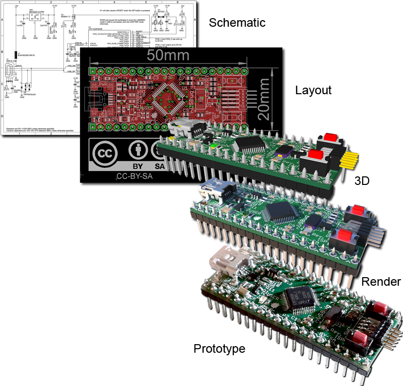
- Tiny size: 50 mm × 20 mm (2" × 0.8"), only 6.2 mm (0.244"") thick (w/o header pins)
- Available with pins for solderless breadboard
- Very low cost
Documentation & Resources
Support Site
As a fully "Open Hardware" project, all design documents are made available in the USBug Github repository.
Make sure you also visit the corresponding Wiki where you will find the most up-to-date information on the project.
Schematic
The schematic can be downloaded in EagleCAD or PDF format from the Github repository.
Layout
The board layout can be downloaded in EagleCAD format from the Github repository.
PCB
All Gerber RS274D files for PCB manufacturing are available from the Github repository.
3D Model
The Sketchup 3D Model can be downloaded from the 3D WareHouse.
Pictures


Videos
Bill Of Materials
| Qty | Value | Device | Parts | Supplier | Supplier Part Number | Manufacturer | Manufacturer Part Number | Description |
|---|---|---|---|---|---|---|---|---|
| 1 | 1M | RES_0603 | R12 | DigiKey | P1.0MGCT-ND | Panasonic - ECG | ERJ-3GEYJ105V | RES 1.0M OHM 1/10W 5% 0603 SMD |
| 2 | 1k | RES_0603 | R4, R9 | DigiKey | P1.0KGCT-ND | Panasonic - ECG | ERJ-3GEYJ102V | RES 1.0K OHM 1/10W 5% 0603 SMD |
| 1 | 1k5 | RES_0603 | R7 | DigiKey | P1.5KGCT-ND | Panasonic - ECG | ERJ-3GEYJ152V | RES 1.5K OHM 1/10W 5% 0603 SMD |
| 1 | 1u/16V | CAP_0603 | C2 | DigiKey | 587-1241-1-ND | Taiyo Yuden | EMK107B7105KA-T | CAP CER 1UF 16V 10% X7R 0603 |
| 1 | 2u2/10V | CAP_0603 | C3 | DigiKey | 587-2983-1-ND | Taiyo Yuden | LMK107B7225KA-T | CAP CER 2.2UF 10V 10% X7R 0603 |
| 1 | 10k | RES_0603 | R3 | DigiKey | P10KGCT-ND | Panasonic - ECG | ERJ-3GEYJ103V | RES 10K OHM 1/10W 5% 0603 SMD |
| 2 | 10n | CAP_0603 | C7, C10 | DigiKey | 445-6855-1-ND | TDK Corporation | C1608X7R1C103K | CAP CER 10000PF 16V 10% X7R 0603 |
| 1 | 10n/500V | CAP_1206 | C8 | DigiKey | 709-1027-1-ND | Johanson Dielectrics Inc | 501R18W103KV4E | CAP CER 10000PF 500V X7R 1206 |
| 1 | 12MHz | CRYSTAL_50X32 | Y1 | DigiKey | 644-1034-1-ND | NDK | NX5032GA-12.000000MHZ-LN-CD-1 | CRYSTAL 12.000000 MHZ 8PF SMD |
| 2 | 18p/50V | CAP_0603 | C4, C5 | DigiKey | 445-1272-1-ND | TDK Corporation | C1608C0G1H180J | CAP CER 18PF 50V 5% NP0 0603 |
| 2 | 20K | RES_0603 | R1, R2 | DigiKey | P20KGCT-ND | Panasonic - ECG | ERJ-3GEYJ203V | RES 20K OHM 1/10W 5% 0603 SMD |
| 2 | 33R | RES_0603 | R10, R11 | DigiKey | P33GCT-ND | Panasonic - ECG | ERJ-3GEYJ330V | RES 33 OHM 1/10W 5% 0603 SMD |
| 1 | 100k | RES_0603 | R5 | DigiKey | P100KGCT-ND | Panasonic - ECG | ERJ-3GEYJ104V | RES 100K OHM 1/10W 5% 0603 SMD |
| 3 | 100n | CAP_0603 | C1, C6, C9 | DigiKey | 478-1239-1-ND | AVX Corporation | 0603YC104KAT2A | CAP CER 0.1UF 16V 10% X7R 0603 |
| 2 | 150R | RES_0603 | R6, R8 | DigiKey | P150GCT-ND | Panasonic - ECG | ERJ-3GEYJ151V | RES 150 OHM 1/10W 5% 0603 SMD |
| 1 | BAT54C | BAT54C | D1 | DigiKey | BAT54C-FDICT-ND | Diodes Inc | BAT54C-7-F | DIODE SCHOTTKY DUAL 30V SOT23-3 |
| 1 | BLM18EG601SN1D | FERRITE_BEAD0603 | L1 | DigiKey | 490-3994-1-ND | Murata Electronics North America | BLM18EG601SN1D | FILTER CHIP 600 OHM 500MA 0603 |
| 1 | BSS84-7-F | BSS84-7-F | Q1 | DigiKey | BSS84-FDICT-ND | Diodes Inc | BSS84-7-F | MOSFET P-CH 50V 130MA SOT23-3 |
| 1 | FTSH-105-01-L-DH | FTSH-105-01-L-DH | P1 | DigiKey | SAM1160-05-ND | Samtec Inc | FTSH-105-01-L-DH | CONN HEADR 10POS DL .05″ R/A SMD |
| 1 | ISP | SPST_SWITCH | S2 | DigiKey | 679-2307-1-ND | APEM Components, LLC | ADTSM32RVTR | SWITCH TACTILE SPST-NO 0.05A 12V |
| 1 | LEFT | HEADER_1X20_LOCK | P2 | DigiKey | WM6420-ND | Molex Connector Corporation | 22-28-4200 | CONN HEADER 20POS .100 VERT TIN |
| 1 | LPC1343FBD48 | LPC1343FBD48 | U1 | DigiKey | 568-4945-ND | NXP Semiconductors | LPC1343FBD48,151 | IC MCU 32BIT 32KB FLASH 48LQFP |
| 1 | MIC5225-3.3YM5 | MIC5225-3.3YM5 | VR1 | DigiKey | 576-2980-1-ND | Micrel Inc | MIC5225-3.3YM5 TR | IC REG 3.3V SOT23-5 |
| 1 | MINI-B USB | MINI-B_USBUX60-MB-5ST | J1 | DigiKey | H2959CT-ND | Hirose Electric Co Ltd | UX60-MB-5ST | CONN RECEPT MINI USB2.0 5POS |
| 1 | POWER | LED_0805 | D2 | DigiKey | 350-2038-1-ND | Dialight | 598-8110-107F | LED TOPLED LED ALINGAP RED CLEAR 0805 SMD |
| 1 | PRTR5V0U2X | PRTR5V0U2X | D5 | DigiKey | 568-4140-1-ND | NXP Semiconductors | PRTR5V0U2X,215 | DIODE ESD PROTECTION SOT143B |
| 1 | RESET | SPST_SWITCH | S1 | DigiKey | 679-2307-1-ND | APEM Components, LLC | ADTSM32RVTR | SWITCH TACTILE SPST-NO 0.05A 12V |
| 1 | RIGHT | HEADER_1X20_LOCK | P3 | DigiKey | WM6420-ND | Molex Connector Corporation | 22-28-4200 | CONN HEADER 20POS .100 VERT TIN |
| 1 | USB | LED_0805 | D3 | DigiKey | 350-2032-1-ND | Dialight | 598-8140-107F | LED ALINGAP YLW CLEAR 0805 SMD |
| 1 | USER | LED_0805 | D4 | DigiKey | 350-2035-1-ND | Dialight | 598-8170-107F | LED ALINGAP GREEN CLEAR 0805 SMD |
| Qty | Value | Device | Parts | Supplier | Supplier Part Number | Manufacturer | Manufacturer Part Number | Description |
Datasheets
- NXP's LPC ARM Cortex M0/M3 32-bit processor:
- Micrel MIC5225 Ultra-Low Quiescient Current 150mA µCap Low Dropout Regulator
- NXP PRTR5V0U2X Ultra low capacitance double rail-to-rail ESD protection diode
- Diodes Inc. BAT54 /A /C /S Surface Mount Schottky Barrier Diode
- Diodes Inc. BSS84 P-Channel Enhancement Mode MOSFET
- NDK NX5032GA 5 × 3.2mm Crystal
- Dialight microLED® SMD LED Selector Guide 598 Series
- APEM ADTS3 Series 3.5 × 6mm Tact Switch
- Hirose UX Series Mini B USB connectors
- Molex KK 100 Header Flat Vertical Breakaway
- Samtec FTSH SMT Micro Header, Samtec FTSH-1XX-XX-XXX-DH-XX-MKT Right-Angle Headers
- MuRata BLM18E Series (0603 Size) EMIFIL® (Inductor type) Chip Ferrite Bead for GHz Noise
- Johanson Dielectrics High Voltage Surface Mount Multilayer Ceramic Chip Capacitors (SMD MLCCs) 250 - 6,000 VDC
- Tayo Yuden LMK107B7225KA-T High Value Multilayer Ceramic Capacitors (High dielectric type)
- Tayo Yuden EMK107B7105KA-T High Value Multilayer Ceramic Capacitors (High dielectric type)
- AVX Surface Mount Multilayer Ceramic Chip Capacitors (SMD MLCCs) X7R Dielectric
- TDK C Series General Applciation Surface Mount Multilayer Ceramic Chip Capacitors (SMD MLCCs)
- Kemet Surface Mount Multilayer Ceramic Chip Capacitors (SMD MLCCs) C0G Dielectric, 10VDC-200VDC (Commercial Grade)
- Panasonic Thick Film Resistors
CPU Variants
NXP's LPC USB ARM Cortex M0/M3 Microcontrollers
Today, 32-bit microncontrollers are outperforming older 8-bit microcontrollers, both in terms of performance, but also in terms of price. Thanks to the ever finer silicon etching capabilities, it is now possible to put more transisors on the same surface, allowing for wider data paths and more complex architectures at a competitive price and comparable power consumption.
Among all 32-bit architectures, ARM Ltd. has clearly one of the leading solution with its low-power "Cortex M" CPU core design. This very energy and size-efficient IP (Intellectual Property) has been adopted by most of the microcontroller manufacturers and has become the de facto standard for embedded 32-bit microcontroller CPU cores.
But beside the CPU core itself, the microcontrollers implementing the ARM Cortex-M architecture also provide more sophisticated peripherals, compared to 8-bit units. Usually, a USB device is integrated in most mid-range devices, while USB host and Ethernet is only available on the higher-end devices.
As a major semiconductor manufacturer, NXP has a large selection of ARM Cortex-M-based devices, among which the upper low-range LPC11Uxx and mid-range LPC13xx devices integrates an USB device interface. But compared to other similar devices, these chips have a unique ROM-based MSC ("Mass Storage Class", aka. "USB memory stick") USB bootloader, which is the main reason for choosing them for the USBug board.
The second reason to choose these USB-èenabled LPCxxxx for the USBug is that the devices using the LQFP48 package are pin-to-pin compatible, so here are all the CPUs that are compatible with the USBug board:
| Group | Function | LPC11U23 | LPC11U24 | LPC1342 | LPC1343 | LPC1345 | LPC1346 | LPC1347 |
|---|---|---|---|---|---|---|---|---|
| Analog | ADC Channels/Resolution | 8×10-bit, 400 kSamples/s | 8×10-bit, 400 kSamples/s | 8×10-bit, 400 kSamples/s | 8×10-bit, 400 kSamples/s | 8×12-bit, 500 kSamples/s | 8×12-bit, 500 kSamples/s | 8×12-bit, 500 kSamples/s |
| Clock | Wakeup from Deep-Sleep/Power-Down | GPIO, WDT, USB | GPIO, WDT, USB | GPIO, WDT Oscillator | GPIO, WDT Oscillator | GPIO, WDT, USB | GPIO, WDT, USB | GPIO, WDT, USB |
| Core | CPU | ARM Cortex-M0 r0p0 | ARM Cortex-M0 r0p0 | ARM Cortex-M3 r2p0 | ARM Cortex-M3 r2p0 | ARM Cortex-M3 r2p1 | ARM Cortex-M3 r2p1 | ARM Cortex-M3 r2p1 |
| Core | Processor Speed | 50 MHz | 50 MHz | 72 MHz | 72 MHz | 72 MHz | 72 MHz | 72 MHz |
| Core | SysTick Timer | 1 | 1 | 1 | 1 | 1 | 1 | 1 |
| Core | Bit-banding | yes | yes | yes | yes | yes | yes | yes |
| Core | Memory Protection Unit | no | no | no | no | no | no | no |
| Debug | Debug Interfaces | JTAG/SWD | JTAG/SWD | SWD | SWD | JTAG/SWD | JTAG/SWD | JTAG/SWD |
| GPIOs | GPIO Blocks | 2×32 pins | 2×32 pins | 4×12 pins | 4×12 pins | 2×32 pins | 2×32 pins | 2×32 pins |
| GPIOs | I/O Pins | 40 | 40 | 40 | 40 | 40 | 40 | 40 |
| Memory | Flash | 24 kB | 32 kB | 16 kB | 32 kB | 32 kB | 48 kB | 64 kB |
| Memory | SRAM | 6/8+2 kB | 6/8+2 kB | 4 kB | 8 kB | 8+2 kB | 8+2 kB | 8+2+2 kB |
| Memory | ROM | 16 kB | 16 kB | 16 kB | 16 kB | 16 kB | 16 kB | 16 kB |
| Memory | EEPROM | 1 kB | 2/4 kB | - | - | 2 kB | 4 kB | 4 kB |
| Packaging | Available Packages | QFP64, QFP48, QFN33 | QFP64, QFP48, QFN33 | QFP48,QFN33 | QFP48,QFN33 | QFP64, QFP48, QFN33 | QFP64, QFP48, QFN33 | QFP64, QFP48, QFN33 |
| Serial Interfaces | UART Blocks | 1 | 1 | 1 | 1 | 1 | 1 | 1 |
| Serial Interfaces | I2C Blocks | 1 | 1 | 1 | 1 | 1 | 1 | 1 |
| Serial Interfaces | SSP/SPI Blocks | 2 | 2 | 1 | 1 | 2 | 2 | 2 |
| Timers | 32-bit Timer Blocks | 2 | 2 | 2 | 2 | 2 | 2 | 2 |
| Timers | 16-bit Timer Blocks | 2 | 2 | 2 | 2 | 2 | 2 | 2 |
| Timers | Watchog Timer Blocks | 1 (Windowed) | 1 (Windowed) | 1 | 1 | 1 (Windowed) | 1 (Windowed) | 1 (Windowed) |
| Timers | PWM Channels | 11 | 11 | 11 | 11 | 11 | 11 | 11 |
| USB Interface | USB Blocks | 1 USB 2.0 FS Device + PHY | 1 USB 2.0 FS Device + PHY | 1 USB 2.0 FS Device + PHY | 1 USB 2.0 FS Device + PHY | 1 USB 2.0 FS Device + PHY | 1 USB 2.0 FS Device + PHY | 1 USB 2.0 FS Device + PHY |
| USB Interface | USB ROM-based drivers | HID, MSC, CDC | HID, MSC, CDC | HID, MSC | HID, MSC | HID, MSC, CDC, FDU | HID, MSC, CDC, FDU | HID, MSC, CDC, FDU |
| Group | Function | LPC11U23 | LPC11U24 | LPC1342 | LPC1343 | LPC1345 | LPC1346 | LPC1347 |
Note however that although they are pin-to-pin compatible and that they can be mounted using the same footprint, these devices may need different firmwares to run, as they integrate different IPs (Intellectual Properties) for the CPU core itself, but also for some peripherals (GPIOs, timers and USB device controller, among others).
FAQ
• How do I get the schematic?
As a fully "Open Hardware" project, all design documents are made available in the USBug Github repository.
• Are your boards RoHS compatible?
Yes, the USBug board are designed to use RoHS-compatible components. However, you should also use RoHS PCB and solder to be fully compliant.
• What chip revision are your boards using?
The USBug board is designed to work with all NXP LPC LQFP48 packaged chips and do not depend on a specific chip revision. Although these chips are all pin-to-pin compatible, you should check for programming specificities and chip errata.
• Are the design files available (schematic, layout, BOM and Gerber files)?
Yes! As a fully "Open Hardware" project, all design documents are made available in the USBug Github repository.
• What is the warranty for your boards?
AS A FULLY "OPEN HARDWARE" PROJECT, THERE IS NO WARRANTY FOR THE PRODUCT, TO THE EXTENT PERMITTED BY APPLICABLE LAW. EXCEPT WHEN OTHERWISE STATED IN WRITING THE COPYRIGHT HOLDERS AND/OR OTHER PARTIES PROVIDE THE PRODUCT “AS IS” WITHOUT WARRANTY OF ANY KIND, EITHER EXPRESSED OR IMPLIED, INCLUDING, BUT NOT LIMITED TO, THE IMPLIED WARRANTIES OF MERCHANTABILITY AND FITNESS FOR A PARTICULAR PURPOSE. THE ENTIRE RISK AS TO THE QUALITY AND PERFORMANCE OF THE PRODUCT IS WITH YOU. SHOULD THE PRODUCT PROVE DEFECTIVE, YOU ASSUME THE COST OF ALL NECESSARY SERVICING, REPAIR OR CORRECTION.
IN NO EVENT UNLESS REQUIRED BY APPLICABLE LAW OR AGREED TO IN WRITING WILL ANY COPYRIGHT HOLDER, OR ANY OTHER PARTY WHO MODIFIES AND/OR CONVEYS THE PRODUCT AS PERMITTED ABOVE, BE LIABLE TO YOU FOR DAMAGES, INCLUDING ANY GENERAL, SPECIAL, INCIDENTAL OR CONSEQUENTIAL DAMAGES ARISING OUT OF THE USE OR INABILITY TO USE THE PRODUCT (INCLUDING BUT NOT LIMITED TO LOSS OF DATA OR DATA BEING RENDERED INACCURATE OR LOSSES SUSTAINED BY YOU OR THIRD PARTIES OR A FAILURE OF THE PRODUCT TO OPERATE WITH ANY OTHER PRODUCTS), EVEN IF SUCH HOLDER OR OTHER PARTY HAS BEEN ADVISED OF THE POSSIBILITY OF SUCH DAMAGES.
• Where is the serial number?
The board itself does not have a serial number printed on it. However, the CPU provides both a Part ID and a Unique ID through either ISP ("In-circuit Serial Programming") or IAP ("In-Application Programming").
• Do you have high resolution pictures of your products?
As a fully "Open Hardware" project, all design documents are made available in the eagleUp USBug Github repository, as well as corresponding Sketchup 3D models and Kerkithea render files.
• Do you have a long-term commitment to production and availability of your boards?
As a fully "Open Hardware" project, all design documents are made available in the USBug Github repository. You are thus able to take all required measures yourself in order to obtain the desired availability.
• I cannot download the manuals or files in general. What to do?
Sorry, can't help with this general problem, try a proven working browser!
• How to erase flash on devices when JTAG/SWD interface accidentally disabled or PLL programmed wrongly by application program that is already in flash?
It is possible to disable the JTAG/SWD interface on the LPC1xxx processors from software. It is also possible to program the PLL wrong so that the processor hangs. If this happens, it can be impossible to communicate with the processor via the JTAG/SWD interface. The reason for this is that the application program in flash starts executing immediately after reset. A JTAG/SWD pod normally takes some time to start connecting to the processor. During this initial connection phase, the application program inside the processor can disable the JTAG/SWD interface or hangs the PLL. The internal flash must be erased to solve this situation. Pull the ISP enable signal low when powering the board. This signal is named "PIO0_1" for LPC11xx/13xx.
Immediately connect the processor UART/USB channel to the ISP program (for example FlashMagic). Erase flash from inside the ISP program. This procedure ensures that the application program in internal flash never executes on the processor after powerup. Also make sure to actually power cycle the processor before entering ISP mode. A warm reset does not always reset the PLL to a known state after reset. Therefore a cold reset is needed, i.e., cycle the power.
• Are your boards EMC tested/certified?
USBug boards have not been EMC tested individually since these are components. EMC test (and CE marking) is only done on final products and the result very much depends on the environment into which it is integrated to.
• Which free graphical libraries exist for NXP's processors?
microBuilder's LPC1114 Code Base software library or LPC1343 Code Base software library support all the main internal peripherals, and drivers for common hardware like I2C or SPI-based EEPROM. The code base includes complete C startup code and an easy to understand make file and linker script for building from the command-prompt on any OS (Yagarto 4.5.0 was used for builds), as well as project files for the open-source CodeLite C/C++ IDE and the commercial GCC-based Crossworks for ARM (useful for HW debugging).
• What software development environment (IDE, compiler, debugger) is recommended for your boards?
USBug does not endorse or include a specific software development environment - sometimes also called IDE (Integrated Development Environment).
We do however have good experience with the following products:
- LPCXpresso IDE. It is designed to operate with low-cost target boards including embedded JTAG/SWD interface on the development board. The LPCXpresso IDE is free and after registration it has a 128 kB limitation. Different upgrades exist to raise the code size limit or completely remove it. It is possible to use the embedded JTAG/SWD interface on the target boards as a JTAG/SWD interface for other boards than the LPCXpresso target boards by cutting some traces. This way, a JTAG/SWD interface hardware will cost only what an LPCXpresso board cost (around 20 EUR / 30 USD),. This is the most cost-effective solution to get a working JTAG/SWD programming/debugging interface.
- Keil - MDK/uVision. There is an 'MDK-Lite (32KB code size limit) Edition' is available for download. Keil has a JTAG/SWD interface called ULINK2 which works great together with MDK/uVision.
- Code Red - Red Suite. Code Red is the supplier of the LPCXpresso IDE (and licensed to NXP) and Red Suite is their own, more versatile version of the development environment. Code Red has a JTAG/SWD interface called Red Probe+. Compare versions here.
- Rowley - CrossWorks with the JTAG/SWD interface CrossConnect. There is a fully-functional version for 30 days evaluation.
- IAR - Embedded Workbench
There are other products/(open source)projects than listed above. These have however not been tested with USBug. The ones in the list above we have good experience from using.
You can also use your favorite editor for editing, GCC for compiling and GDB for debugging. This setup require experience and knowledge.
Note that most of our sample applications have been created either for the LPCXpresso IDE or Keil uVision. It is not a very big job to port project settings from one development environment to another, but you are then on your own to provide free support for.
As for debugging, the use of a JTAG/SWD interface and a debugger integrated with the development environment is recommended. This setup gives the most powerful tool to start your program development.
Each software development environment listed above has accompanying JTAG/SWD interfaces. Segger has a very versatile JTAG/SWD interface called J-LINK, which works with many development environments. However, always check with the development supplier of your choice before purchase if J-LINK is supported. If you qualify for it (it should be the case if you are using it for hobby), you may check the relatively cheap J-Link EDU offer.
Most (cheaper) JTAG/SWD interfaces connect to the development PC via the USB interface. Only more expensive interfaces support Ethernet interfaces.